Foreign Insulators
by Marilyn Albers
Reprinted from "INSULATORS - Crown Jewels of the Wire", November 1980, page 4
Alice Springs and the Overland Telegraph Line
In last month's
article I touched briefly on the Overland Telegraph Line in Australia, and the
fact that Robert Chiantelli (Monterey California) had found some of the old
porcelain insulators from that line while visiting in Alice Springs. Since then
Mr. N. R. Woodward (Houston, Texas) has supplied me with a trade journal, dated
February 1939, called The Telecommunication Journal of Australia, published by
the Postal Electrical Society of Victoria. In it was this fascinating story
about Alice Springs and the construction of that same Overland Telegraph Line.
Another article called The New Trunk Insulator went on to explain why this
original design of insulator was eventually replaced by one that provided more
insulation resistance. If you have Australian porcelains in your insulator
collection you will probably recognize both of these designs, and after reading
this, you will appreciate them more!
Since the objective of the Postal
Electrical Society is to promote diffusion of knowledge in communication
services, editors are welcome, in fact encouraged, to use any article from the
Journal, provided no more than one third of it is quoted, and proper credit is
given. The articles are well written and easy to read. The parts I left out had
to do with descriptions of the town of Alice Springs, its people, crops and
flowers, trucks getting stuck in mud holes after a good rain, and mail service
by camel! That we can do without!
The following pictures show some of the
original old insulators from the Overland Line. In the first two photos we see
some from Robert's collection. Counting slight variations in color (from pure
white to a kind of putty color) and also in measurements, he claims he has found
20 different ones. The third photo shows those in my collection, the number
being subject to change after having met Robert at the Bakersfield Show!
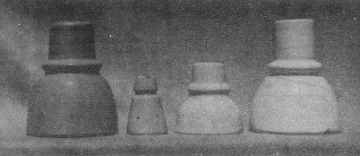
Picture
#1
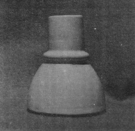
Picture #2.
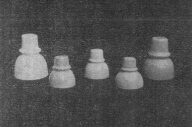
Picture #3.
Alice Springs and the Overland Telegraph Line
R. C. M. Dale
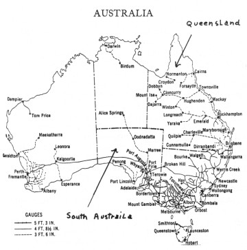
The name "Alice Springs" is really a misnomer, because the deep
pool of water after which the place is named is not a "spring" but a
soak. The town, a panorama of which is given below, is in the centre of the
continent on the Overland Telegraph Line between Adelaide and Darwin. The
locality was given its name by a party engaged on the construction of the
Overland Telegraph Line in 1871 when they sighted the big, deep waterhole in the
bed of the dry creek or river now known as the River Todd.
The Todd only flows after each rain, and at this place there is a large
outcrop of granite rocks. The swirling of the quickly flowing water keeps this
big hole washed out and leaves it full of water. Quite good soakage water can be
obtained anywhere in the creek at about six feet down, and this soakage keeps
the hole full of water, and because the hole does not dry out, it was probably
thought by the party that there must be a spring at that place. There are,
however, many springs in the MacDonnell ranges, but none at the particular spot
after which the old Telegraph Station was named.
Although the continent was crossed for the first time by the explorer
(McDouall Stuart) in 1862, less than ten years later a telegraph line had been
completed practically along the route taken by him. In the late 1860's there was
great rivalry between Queensland and South Australia as to who should have the
honour of linking their telegraph system with the cable being laid from
Singapore to Darwin. Each wanted the other Australian colonies to support the
project from their particular point of view. When in June, 1870, no agreement
had been arrived at and the Cable Company seemed to favour the land line being
constructed from Darwin to Brisbane, the South Australian Government, evidently
realizing that some drastic action was necessary if they were to have the line
in their State, made an offer to the Cable Company to build a telegraph line
from Adelaide to Darwin (1975 miles) and have it completed by the time the
Company had completed their cable, this being estimated at eighteen months from
the time of the offer. The offer, which meant that the telegraph line had to be
constructed at the rate of 110 miles per month, was accepted, and heavy
penalties for non-completion of the line in the time were provided for in the
agreement.
Actually it was not until about the middle of August that year that the
construction was commenced. The route was divided into three sections -- from
Port Augusta to latitude 27 deg. S. (about 60 miles north of where Oodnadatta is
now, a distance of 550 miles), from 27 deg. S. to 19 deg. 30 mins. S.
(approximately where the present town of Tennant Creek is, about 570 miles), and
thence to Darwin, approximately 650 miles. The first section was in more or less
settled country and provided very little difficulty, the northern section had
some difficulties but not very great, but the centre section was in practically
unknown country and therefore was the most difficult. Each section was
subdivided into many sub-sections, and a party allotted to construct each
sub-section. A small exploring party went ahead of each main party and marked
out the route to be taken. The equipment of each party included 15 horse wagons,
17 bullock drays, one bullock wagon, five express wagons, 165 horses and 200
bullocks. A depot was established at the Finke River (about 830 miles from
Adelaide) for the provision of fresh meat for the men working on the adjoining
sections, and 2000 sheep were sent there. It must be remembered that all the
material, provisions, etc., had to be hauled from either Port Augusta or Darwin
by horse, bullock vehicle, or camels, and some idea of the difficulties
experienced can be realized by the fact that it took Harvey's party, who
constructed one of the central sub-sections, eight months to reach the beginning
of their section.
It was far too big a job to be done in the time, and when the period had
expired (December, 1871), there were still many gaps in the line. A delay had
also occurred in the cable construction, and although not far off completion,
the cable was not completed on the contracted date. A compromise was reached
regarding the infliction of penalties, which were considerably reduced but not
entirely abolished, and the South Australian Government redoubled its efforts,
but it was not until 22nd August, 1872, that the last gap was closed and
telegraphic communication established between Australia and England. The total
cost of the line was £479,154.
The original line was a 7/14 stranded iron wire conductor, and although most
of it was removed and replaced by a 400 lb. G.I. conductor many years ago, there
are still some small sections of the original wire in use.
During October, 1938, it became necessary to remove a small piece of the
original wire in connection with the establishment of a Telephone Office at
Finke, and it was found that the old wire was in perfect condition and not
showing any signs of deterioration. Several types of insulators appear to have
been used. One type was of porcelain, about 4-1/2 inches across at the bottom,
but having a metal top, two inches in diameter, screwed on to the
porcelain.
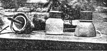
Old types of insulators used on the original Overland Telegraph Line
and a piece of the original iron wire. The two outer insulators are the
metal armoured type and the hole. through which the wire was passed can be
seen in the top of the centre insulator. |
A metal plate bolts on to the metal top, and two holes, through which a wire
could be passed were formed when the plate was screwed down. Apparently only one hole was used,
but the tightening of the bolt held the wire firmly between the plate and the
metal top of the insulator. There were thus no tie wires necessary with this
type. Another type is similar to the present day trunk line insulators, a little
smaller, but completely covered with a metal armour. The metal armour is shaped
exactly like the insulator, and the wire was tied to this similarly as is done
on present day porcelain insulators. The porcelain was set into the armour by a kind of
cement, and a thread was provided in the porcelain for the spindle. A number of
these insulators are still to be seen lying along the line, and although over 66
years old, do not show the slightest sign of rust or deterioration.
In many
instances the line did not take a direct route between various points, but followed creeks
and watercourses. The reason for this was that most of the poles
were cut from the timbers growing along these watercourses, and also that it was
necessary to follow them in order to obtain water. However, the white ants soon
showed their presence, and although there are some of the original butts still
to be seen besides the present iron poles, most of the wooden poles had very
short lives, perhaps only of a few years' duration. In 1880, re-poling with
Siemens and Oppenheimer poles was commenced in places, but it was not until
1898, when a 265 lb. copper conductor was added that the line was fully
iron-poled. During the erection of the copper wire and the final iron poles, the
line route was considerably straightened, now following a more direct route
and not keeping to the watercourses. No more wires have been added since then,
but the methods of telegraphy used have kept abreast of the times and enabled
the growing volume of traffic to be handled satisfactorily.
Originally the
messages were repeated by hand at several stations along the route, and in between these stations were many others at which linemen were located. These
latter were placed at points where water could be obtained, and varied in
distance from. 95 to 180 miles apart. As the country became opened up and telegraph systems improved, it became possible to abolish many of these
stations, and one by one they have passed out of the Department's control. Some
are now police stations, some are cattle station homesteads, and others railway
stations. Today the only repeater stations apart from Port Augusta, in the
circuits, are Alice Springs on the copper line, and Marree, Powell Creek and
Alice Springs on the iron. Besides these the only other stations remaining in
the Department's hands are Tennant Creek, Daly Waters and Katherine.
In time,
hand repeating gave way to "pole changer" repeaters, and about 1926 relay
repeaters were installed at
the three repeater stations.
Nearby the pool which the first party had mistaken for springs, the Alice Springs Telegraph Station was built. For many years
it was a lonely outpost, receiving its mail only once every six weeks or two
months. At first it came by packs and camels from Port Augusta, later from Marree,
still later from Oodnadatta, and in 1927 the railway line was completed to
Stuart Town, two miles south of Alice Springs Telegraph Station. Although Stuart Town was surveyed in the late 1890's, it did not
take shape until the completion of the railway. With the growth of the town it
became necessary to establish an official office, and in 1932 the old telegraph
station at Alice Springs was closed and a new post office opened in what was
originally Stuart Town, but which now had its name changed to "Alice
Springs."
It is not often that we get a good downpour of rain, but we
usually manage one good one each year. On 19th February, 1938, from two to five
inches of rain fell from Alice Springs to Oodnadatta. Rivers ran bankers, and at
one time the Alberga was flowing 16 feet above the railway bridge and over half
a mile wide. Communication with Adelaide was completely cut off for several
days, and the train service was not restored until six weeks later. Miles of
railway line was washed away and many sections of the telegraph line carried
away in the floods. Where the telegraph lines cross the Alberga there were two
28 ft. iron beam poles, but after the water had subsided they were found in
different places about a quarter of a mile downstream, one end of each just
showing through the mud and the other end under between six and seven feet of
mud and silt. Some food supplies were brought to Alice Springs by aeroplane, but
by the time the train service had been restored, there were many items which
were unprocurable in the town, despite that rationing had been resorted to.
When
the waters had subsided sufficiently to allow movement, Mr. E. Colson, of Bloods
Creek Telephone Office (the nearest resident to the Alberga River), offered to
attempt repairs to the lines, and set out on camels to do the job. Progress was
slow, as it is a fair day's ride to do 30 miles by camel, especially in wet
country, and stoppages were frequent in order to clear debris away from the
lines. In addition, many detours had to be made to get across creeks and rivers
which were still flowing, and he estimated that to traverse the 100 miles of
line from his place to Oodnadatta, he traveled 160 miles. At the Alberga
crossing he and three natives worked most of one day in water up to their arm-pits, rigging up temporary supports for the line. These were tripods about 10
feet high, and were constructed from timber cut from the trees growing nearby. Insulators were tied on to them, and the lines in turn
tied to the insulators. Altogether it took eight days to travel and repair the
105 miles of line between Bloods Creek and Oodnadatta.
On the south side of the
Alberga no wire was left on the poles (which were washed out and bent all
shapes) for a quarter of a mile, the wire evidently having been caught and
carried away by debris which was washed down. Many miles of railway line and two
bridges were washed away, and it took nearly five months to repair the permanent
way. It is. interesting to note that none of the railway bridges carried away
have been replaced. Instead, the line is laid on a built-in rock foundation in
the bed of the creek or river. Excavations are made to some depth in the river bed and stone or rock firmly packed therein and the
line laid on top of the stone. This method was first tried out when the Finke
bridge carried away about six years ago, and has proved to be quite effective
for, at the most, the damage amounts only to a short length of railway line being
twisted, instead of an irreparable costly bridge.
The New Trunk Insulator
R. M. Osborne, M.E.E, A.M.I.E.E.
With the extension of the practice of dialing over trunk lines, troubles
have been experienced on account of the large variation in the insulation
resistance of the aerial circuits used. Some dialing lines, in wet weather, have
an insulation resistance of 10,000 ohms or even less, and become unworkable, and
in 1936 it was decided that the standard trunk insulator should be re-designed
in order to effect, if possible, an improvement in this state of affairs. It was
recognized that, although there are several sources of loss in a telephone
insulator, by far the most important one at voice and telegraph frequencies is
surface leakage between wire and pin, and the object of the designers was, therefore, to reduce this effect.
With a clean insulator the surface leakage,
even in wet weather, is small, but, as dirt accumulates, a semi-conducting path is
formed on the surface if the atmosphere is moist, particularly if the dirt
includes salt or carbon. The resistance of this path depends upon its length and
cross-sectional area in the same way as the resistance of any conductor depends
upon these variables, and it is therefore desirable to make the length of the
path as great as possible whilst, at the same time, keeping its cross-section
area as small as possible, i.e., by keeping the circumference of the insulator
as small as possible.
This result is partially achieved in many insulators by using two skirts.
The trunk insulator which has been standard in Australia for many years is one
design which incorporates this feature, and so is the B.P.O. trunk insulator.
These two designs are shown in Figs. 1 and 2. Examination of them shows that the
B.P.O. insulator provides a longer leakage path between wire and pin (32 cms. as
compared with 23 cms.), and at the same time the average diameter of the leakage
surface is considerably less (4.60 cms. as compared with 7.54 cms.). Thus, if
each of the insulators has an equal thickness of similar deposit upon it, the
surface resistance of the B.P.O. insulator will be nearly 2.3 times as great as
that of the Australian trunk insulator. In addition, exposure tests conducted at
the Research Laboratories indicated that the external surface of the Australian
insulator which curves outwards is more likely to accumulate dirt than the
straight vertical sides of the B.P.O. design.
It was therefore decided to use
the B.P.O. insulator as the basis for design, but to attempt to make it suitable for use
with wooden spindles which, in Australia, are more economical than steel
spindles. The use of wooden spindles would necessitate increasing the diameter, for it would not be practicable to
obtain a sufficiently strong wooden spindle to fit the thread of the B.P.O.
design.
This increase of diameter would tend to reduce the surface leakage resistance
and also would increase the weight of the insulator; it would therefore be
undesirable. Instead of abandoning the wooden spindle the designers decided to
depart from the B.P.O. practice and eliminate the second skirt. They argued
that, although by doing so they would reduce the length of the leakage path,
they would also reduce the average diameter of the insulator, and thus the two
effects would partly cancel out. Furthermore, they believed that the outer surface, which is continually washed by rain, is the most important part, and that
the elimination of the inner skirt would not be as serious as might be imagined.
To obtain the maximum benefit, however, a wooden spindle of minimum practicable
diameter was designed for use with the new insulator, the final design of which
is shown in Fig. 3. It is hoped that, when tests have been completed, this
insulator will become the Australian Standard Trunk Insulator.
The length of the
surface leakage path of this insulator is slightly less than that of the old
trunk insulator (18 cms. as compared with 23 cms.) but its average diameter is considerably less (5.08 cms. as compared
with 7.54 cms.) and therefore its theoretical surface leakage resistance is greater than that of
the old design. Furthermore, as stated above, a large proportion (57 per cent.)
of its leakage path is exposed to the cleansing action of rain. With the old
trunk insulator, this proportion is 87 per cent. and with the B.P.O. insulator
it is 32 per cent. The designers hope that this feature of the new insulator
will largely compensate for the higher theoretical leakage resistance of the
B.P.O. insulator.
After the design had been completed, it was decided to conduct
field tests by installing the insulators on the Melbourne-Geelong trunk route
but, before this was done, the decision to scrap this route made other plans
necessary, and it was decided to equip certain lines between Melbourne and
Dromana which were known to have very low insulation resistance during periods
of high humidity. It was. intended to equip one circuit with the new insulators
made of porcelain, and one circuit with B.P.O. porcelain insulators, and to
compare the results obtained with the standard Australian porcelain insulators
erected on the same poles. It was then thought advisable to make some of the new
insulators in glass in order that the value of this material for the purpose
could be examined. The Australian Glass Go. agreed to co-operate but pointed out
that the new design, although suitable for porcelain, was not ideal for glass
because of the cooling stresses likely to be set up in the body of the
insulator. They submitted a design which gave the same leakage path but which,
they considered, would be better for glass, and the Department purchased
sufficient of these insulators to equip a circuit between Melbourne and Dromana.
Fig. 4 shows a glass insulator of the design tested.
[At the time these tests were being made (1936) Australian Glass Company's
insulators would be marked Agee (AGEE). I don't recall seeing any insulators so
marked with this design. It is not a CD 130.7, though similar. Maybe it was discarded, and later evolved into the 130.7 we all know, and marked A.G.M.
M.A.]
The installation of the insulators on the Melbourne-Dromana circuits was completed in March, 1938, and each of the
circuits was connected to the Research Laboratories by an underground cable
pair between the Glenhuntly cable head at the Melbourne end of the circuits,
and the Laboratories, and a recording galvanometer was arranged to record the
insulation resistance of each of the circuits. The method of connection did not
affect the usefulness of the circuits for their normal traffic, and they were not, therefore, withdrawn
from service. Before tests commenced, the insulators on these lines were cleaned
by spraying them from the ground.
In July, 1938, the first analysis of the
results was made. As was known, the insulation of the various lines varied
considerably with the humidity, and in order to compare the results, it was
therefore necessary to compare the readings at equal humidities, and for the
purpose of these tests, the readings at high humidities are, of course, the most
important because it is under these conditions that lowest insulations occur.
Some variations occurred in the day by day readings, but the lowest insulation
resistances recorded at any time were as under: --
B.P.O. Standard
|
38,000 ohms.
|
Australian Single Skirt--
|
|
Porcelain
|
34,000 ohms.
|
Glass
|
14,000 ohms.
|
Australian
Double Skirt (old design)
|
5,000 ohms.
|
These readings are the overall readings
between wires of the lines which are approximately 46 miles long; the lowest
readings at other humidities were in about the same order. For example, at 80
per cent. they were:--
B.P.O. Standard
|
450,000
|
Australian Single Skirt--
|
|
Porcelain
|
450,000
|
Glass
|
160,000
|
Australian Double Skirt (old de sign)
|
50,000
|
These results
are very satisfactory and, so far, confirm the designers' belief in the single
skirt design. It would be unwise to be unduly optimistic until further results
have been obtained and the effect of weathering has been ascertained, but on the
results so far, the Department has felt justified in purchasing large supplies
of trunk insulators to the new design. This will, of course, introduce
complications such as are always met when an old standard is replaced by a
new, but it is felt that the advantages to be obtained are very real and far
outweigh the objections.
The reason for the low value of the glass insulator is not very clear at
present, but it is possibly due to the presence of cracked insulators on the
line. During installation, some of these insulators cracked and a number actually
broke. Whatever the reason, however, the results so far reflect some
inferiority of the glass insulators installed for test, which may or may not
become more pronounced as the tests proceed.
It is possible that an extra groove may be added to the design of Fig. 3, but
unless future tests cause opinions to be modified considerably, it is probable
that no drastic alterations to it will be made and that it will become the new
Departmental Standard, and will be known as Insulator, Trunk, L.S. (Long Skirt)
to distinguish it from the present Trunk Insulator. The new wooden spindle for
use with it has already been designed, and designs for the necessary steel
spindles are in course of preparation.
- - - - - - - - - -
Many thanks to Mr. Woodward for sharing this information with us!
|

)
)
)
)
)
)
)
)
)